Electrical Cable Tray Fixing CAD DWG File with Planning
This Cable Tray Fixing CAD Drawing File presents a detailed DWG layout suitable for electrical design and cable management systems. The plan includes fixing details, tray dimensions, and alignment
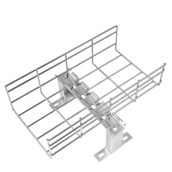
Wire Basket Tray System
Each tray section should be bonded to an adjoining section using listed bonding jumpers or a continuous ground wire and clamps (such as a copper ground bolt). Powder coated tray requires the removal of
Cable Tray Installation CAD Blocks | DWG Electrical Layout
Download a comprehensive set of Cable Tray Installation CAD Blocks in DWG format, ideal for electrical engineers, MEP designers, and industrial layout planners.
Best Practice Guide to Cable Ladder and Cable Tray Systems
Wall support brackets (Figures 12) are an effective way of fixing any width of cable ladder or cable tray, running either vertically or horizontally, to a vertical support.
Cable Tray Installation Guidelines | PDF | Galvanization
It includes diagrams showing how to mount cable trays on walls using pre-fabricated flanges or channels. The document outlines steps for laying cables, including
Cable Tray Technical Guide A practical guide to product selection
Cable tray length is selected based on the load to be supported, the distance between the supports (also referred to as the span), and handling and installation constraints.

CABLE BUS INSTALLATION MANUAL
This series of flanges are used to provide an weatherproof seal where the cable bus makes a transition through a wall, floor, or where cable bus housing is connected to an outdoor enclosure as required
LEGRAND CABLE TRAYS TECHNICAL GUIDE
If it has excellent electrical continuity and is integrated in the installation''s equipotential bonding system, a metal cable tray reduces the coupling''s impact and thus contributes to good EMC of the electrical
INSTALLATION GUIDE
To maximize the rigidity of the ladder tray, the section should be laid out so that the splice locations are between the quarter point of the tray [1.5 meters (4.8'') for a 6 meter section] and the location of the
CABLE TRAY SYSTEMS GUIDE
Some applications may require the cable tray to support the weight of a single, dead object in addition to the cable loads. Specifications typically require this to be applied at the midpoint of the span between
Cable tray manual
All the technical information developed by the 1973 NEC®Technical Subcommittee on Cable Tray for Article 318 - Cable Trays was based on cable trays with side rails and this technical information is still
Micro-Modular & Edge DC
Prefabricated micro-modular data centers and edge pods, scalable from 5 to 50 racks, ready for 5G and edge AI workloads.
Immersion & Liquid Cooling
Single-phase immersion cooling tanks and direct-to-chip liquid cooling switches, achieving PUE below 1.1.
AI Servers & Racks
GPU-accelerated AI servers, high-density server racks, and network cabinets optimized for AI/ML workloads.
DCIM/EMS & Cable Bridge
Real-time data center infrastructure management, plus overhead cable trays and fiber bridges for structured cabling.