Implementation of Optocoupler Test Fixture in Incoming Quality
The proposed automated optocoupler test fixture design is to over-come the existing manual testing of optocoupler with related test plan to demonstrate the optocoupler test fixture.
Testing Methods for Optocouplers
The document describes 3 methods for testing opto-couplers to determine if they are functioning properly or bad. The methods involve using a multimeter to measure resistance or voltage across the
HOW TO TEST OPTOCOUPLER ICs CHIPS test integrated circuit
1) Input Checking. Set the multimeter to diode test Function and connect test leads as photo. Picture number one is forward biasing to LED so we will see voltage across LED = 1.077V
TesT & MeasureMenT
Combination test Expanded test method for optocouplers Optocouplers must be tested for compliance with specified parameter values by means of function as well as in-circuit tests.
Combination test Expanded test method for optocouplers
Optocouplers must be tested for compliance with specified parameter values by means of function as well as in-circuit tests. A basic characteristic of an optocoupler is DC isolation between its input and
Comprehensive Guide to Testing Methods for Optocouplers
To determine the quality of an optocoupler, one can measure the forward and reverse resistance of its internal diode and transistor in-circuit. More reliable detection methods include the
Optocoupler Tester Circuit: Build, Test & Troubleshoot
Build a simple DIY optocoupler tester circuit with two LEDs and a 3.7V battery. Test 4-pin and 6-pin optocouplers instantly, no instruments needed. Full diagram included.
Guideline for Optocoupler Ground Radiation Testing and
This guide is intended to support insertion of these optocouplers into spaceflight applications and to recommend ground test protocols. The first guideline principle that should be followed is a serious
Demystifying Isolation Certification Standards: Optocouplers vs
To differentiate between isolation performance in oil vs in air, IEC 60747-17 specifies that the isolation performance of a digital isolator is tested in both oil (VIOSM) and in air (VIMP). Whereas the
How to accurately detect the quality of optocoupler (optocoupler
Correctly detecting the quality of optocoupler components can help engineers promptly troubleshoot faults and avoid potential system issues. Below, we will provide a detailed introduction
Measuring Optocouplers using Bode 100, and Picotest M3522A
In Summary, the OMICRON Lab Bode 100 Vector Network Analyzer, when utilized alongside the Picotest J2200A Optocoupler CTR Module and Picotest M3522A 6 1/2 Digit
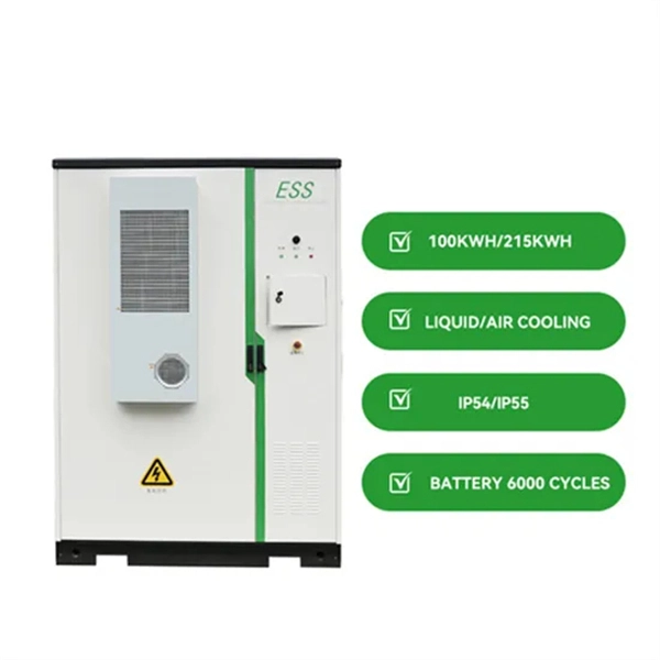
Micro-Modular & Edge DC
Prefabricated micro-modular data centers and edge pods, scalable from 5 to 50 racks, ready for 5G and edge AI workloads.
Immersion & Liquid Cooling
Single-phase immersion cooling tanks and direct-to-chip liquid cooling switches, achieving PUE below 1.1.
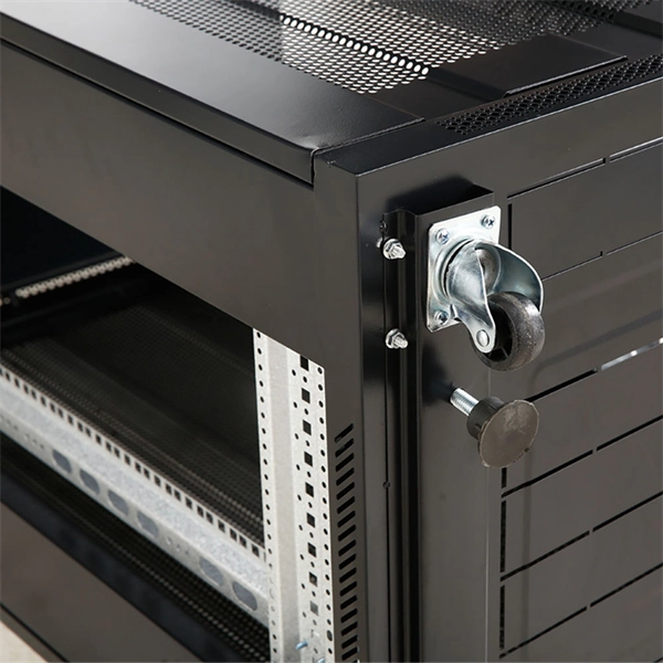
AI Servers & Racks
GPU-accelerated AI servers, high-density server racks, and network cabinets optimized for AI/ML workloads.
DCIM/EMS & Cable Bridge
Real-time data center infrastructure management, plus overhead cable trays and fiber bridges for structured cabling.