Employee Benefits & HR Compliance Platform (HSA, FSA, HRA) | Clarity
From designing a benefit program with your broker to online enrollment, we have you covered. Employee education, integration with providers, and consumer payment solutions are all
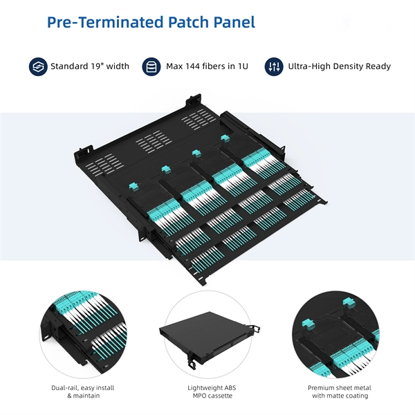
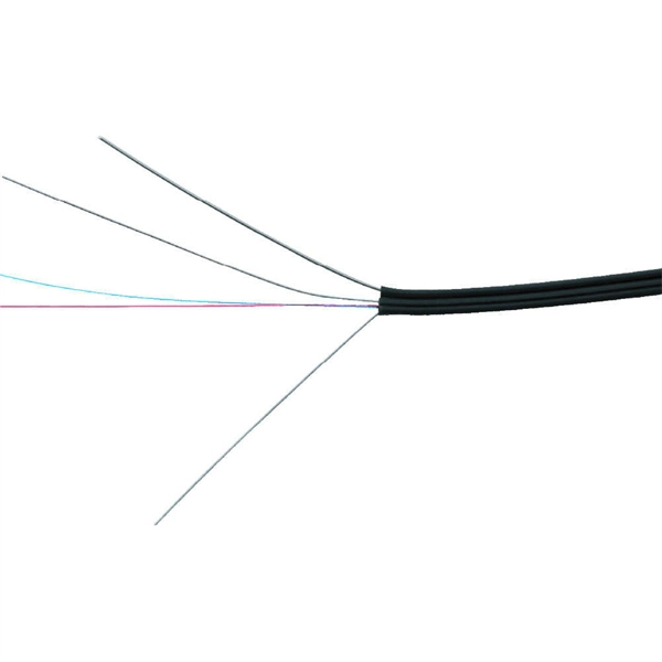
Fibre Optic Cabling Loss Limits Explained – Trend Networks
Learn about fibre optic cabling loss limits & how to calculate them. Gain insights from experts on acceptable loss for cabling projects & explore the standards.
Clarity
Please enter your account details. By continuing you consent to the Clarity General Terms of Business and the Clarity CFD Terms & Conditions. Don''t have an account? Create your Clarity account. Forgot
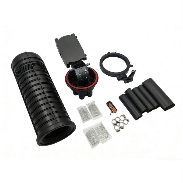
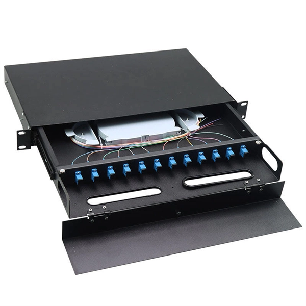
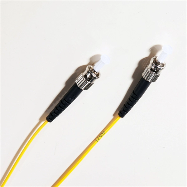
How to Splice Fiber Optic Cable – Step-by-Step Fusion Splicing Guide
Acceptable fusion splice loss: ≤0.1 dB per joint (per ITU-T G.652.D). If loss > 0.15 dB, re-cleave and re-splice. Slide the splice protector over the joint. Place in heat oven. Wait for completion
Participant Account
If you have personal benefit accounts with Clarity (HSA, FSA, HRA, SmartRide), you can link your personal profile to your administrative profile to access all of your Clarity benefit information under
ITU-T Rec. L.400/L.12 (02/2022) Optical fibre splices
The increased splice loss caused by the difference in fibre characteristics is given in Appendix II and can be added to the attenuation values in test 8.2.1 of Table 1 as an estimation of the true loss in case of
Optical Fiber Link Performance Testing | PDF
For backbone links, attenuation is calculated using an provided equation that considers fiber type, length, connectors and splices, and graphs depict
Optical Fiber Attenuation Calculator
Compute fiber attenuation using input and output power. Convert length units, then estimate loss per kilometer. Export CSV or PDF for clean records and sharing.
Clarity Goes Live
Once you attend the training, please give our HMIS team 3-5 business days to set up your account. You will receive an email with the above instructions to log on when the account is available.
What Should Attenuation Values at the Splice Points Be In Fiber-Optic
What should attenuation values at the splice points be in fiber-optic cables? ANSWER: A good splice should have an attenuation of less than 0.3 dB over the entire distance. Many factors
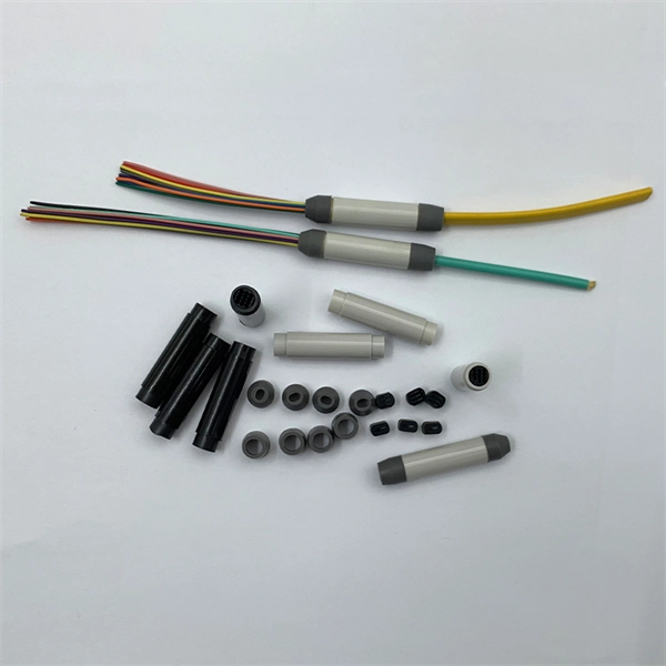
Multimode Splice Loss
When splicing similar fibers, typical splice loss values (less than 0.1dB fusion or 0.2 dB mechanical) are expected. However, when splicing dissimilar fibers, additional factors must be taken into account
Guidelines On What Loss To Expect When Testing Fiber Optic Cables
For each splice, figure 0.3 dB for multimode mechanical splices (0.3 max per EIA/TIA 568) and 0.15dB for singlemode fusion splices.
What Is Acceptable dB Loss for Fiber Optics?
Acceptable dB loss for fiber depends on the component you''re measuring: a single mated connector pair should lose no more than 0.75 dB, a fusion splice should stay under 0.3 dB, and fiber
Permanent Link Testing of Multimode and Singlemode Fiber
The ANSI/TIA/EIA-568-B standards designate the allowable attenuation coefficients for the different cable types along with the loss for fixed connectors as 0.75dB per mated pair, and the allowable loss

Clarity
The financial aid platform purpose built to help schools attract, enroll and retain modern families.
Guidelines On What Loss To Expect When Testing
For each splice, figure 0.3 dB for multimode mechanical splices (0.3 max per EIA/TIA 568) and 0.15dB for singlemode fusion splices.
newportallogin.claritybenefitsolutions
You can now use your Clarity Mobile App credentials to log in. If you have not registered on the app, you will need to register once you choose Employee Benefits or Lifestyle.

Is That Splice Really Good Enough? Improving Fiber Optic Splice
It is recommended that the results and conclusions of this study be used or the basis of an industry-wide specification for qualifying optical splice loss measurement systems and specifying optical splice loss

Login | Clarity
You may continue to browse the portal in read-only mode. We appreciate your patience during this time. Once the outage is completed you will no longer receive this notification.
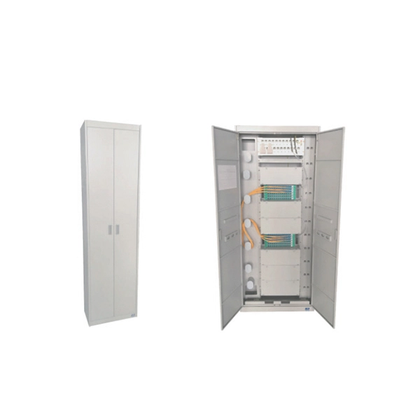
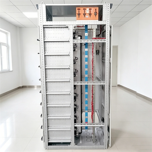
Micro-Modular & Edge DC
Prefabricated micro-modular data centers and edge pods, scalable from 5 to 50 racks, ready for 5G and edge AI workloads.
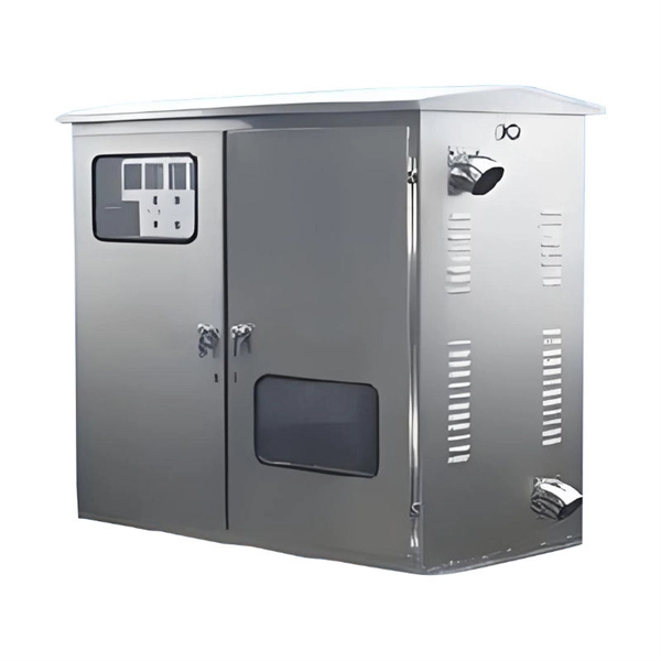
Immersion & Liquid Cooling
Single-phase immersion cooling tanks and direct-to-chip liquid cooling switches, achieving PUE below 1.1.
AI Servers & Racks
GPU-accelerated AI servers, high-density server racks, and network cabinets optimized for AI/ML workloads.
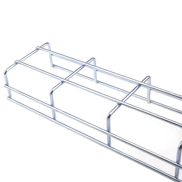
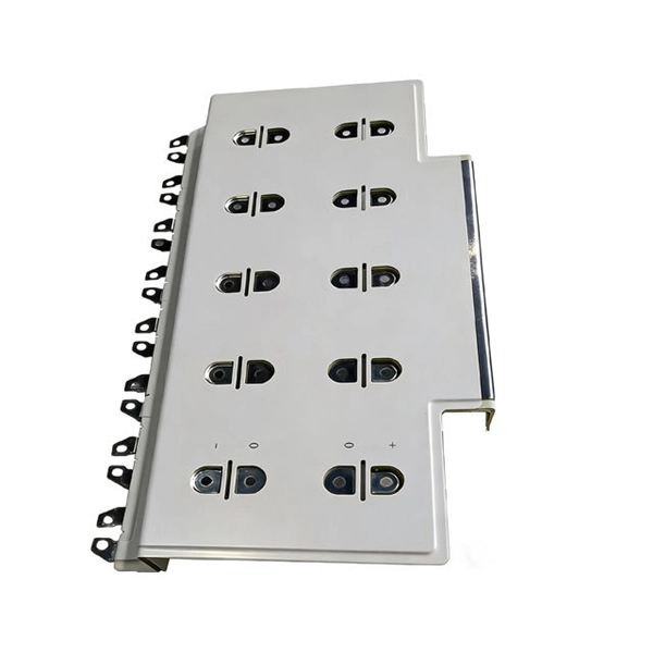
DCIM/EMS & Cable Bridge
Real-time data center infrastructure management, plus overhead cable trays and fiber bridges for structured cabling.