Optical Splitter Insertion Loss Table | PDF | Electronic
The document contains tables listing the insertion loss in dBm for various splitting ratios of an optical splitter, ranging from 1% to 99%. It also includes formulas for calculating insertion loss based on the
How to Calculate Splitter Loss in Optical Fiber
Furthermore, considering our typical example of the perfect Ix2 splitter, the two outputs will each have half of the power fed into them, resulting in an apparent 3 dB loss. However, in real-world
Basic Knowledge about Split Ratio and Insertion Loss of Optical Splitter
Excess loss is the ratio of the optical power launched at the input port of the splitter to the total optical power measured from all output ports. It assures that the total output is never as high as
Ultimate Guide 2023: PLC Splitter / FBT Fiber Splitter Loss Chart
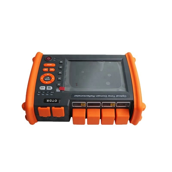
How to measure fiber optic splitter insertion loss with calculation? The maximum allowable insertion loss for an optical splitter used in a PON system can be determined by using the
PLC Splitter and download the loss chart of PLC splitter
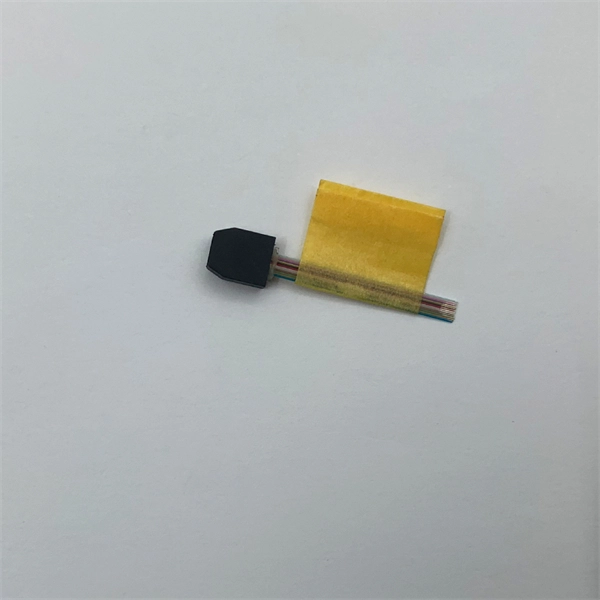
A splitter with 1×2 certain ratio configuration means that it has one input and two outputs. There are 1×4 plc splitter, 1×8 plc splitter, 1×16 plc splitter, 1×32 splitter, and so on. Here is a table of
Splitter Ratios: 1:8 vs 1:16 vs 1:32
Splitter ratios affect insertion loss and serviceability. Common ratios: For cascades, add losses and validate margin using the Optical Budget tool. Compare typical losses and use‑cases;
PON Splitter Ratio Loss Calculator
Press here to calculate with Number of Splitter Ports.
Understanding Optical Splitter Loss
Understanding splitter ratios and insertion loss is fundamental to building a reliable fibre optic network. The key takeaway is that every split reduces optical power, and this loss must be
Optical Splitter Loss Calculator
Estimate optical splitter losses for fiber building projects fast. Include connectors, splices, excess loss, and margin safety. Export results to reports for clean client handoffs.
Fiber Optic Loss & Power Calculator
Splitter loss values are "Typical" and include a connector in and out. These values are approximate and should not be exceeded by more than 1-1.5 dB, which could indicate dirty connectors, bad splices, or
Micro-Modular & Edge DC
Prefabricated micro-modular data centers and edge pods, scalable from 5 to 50 racks, ready for 5G and edge AI workloads.
Immersion & Liquid Cooling
Single-phase immersion cooling tanks and direct-to-chip liquid cooling switches, achieving PUE below 1.1.
AI Servers & Racks
GPU-accelerated AI servers, high-density server racks, and network cabinets optimized for AI/ML workloads.
DCIM/EMS & Cable Bridge
Real-time data center infrastructure management, plus overhead cable trays and fiber bridges for structured cabling.