Use of Bus lines
A Bus line is a path to which terminals (Bus Entry objects) can be connected for the input and output of electrical signals. A Bus allows you to enclose multiple connections in a single graphic symbol,
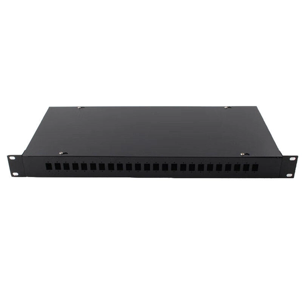
Diagram of the main electrical connection bus line.
... includes transmission buses, distribution bus lines, and wind-solar hybrid components. The main electrical connection circuit diagram is shown in Figure 4.
Three Phase Bus Line Diagram: Single-line
A three-phase bus line diagram typically displays the three phases—referred to as A, B, and C phases—alongside key components like transformers, circuit breakers, and the busbar that
Square D I-Line and Power-Zone Busway Systems Catalog
This catalog includes information on features, construction, application, installation, electrical data, busbar configuration, wiring diagrams, and dimension drawings for Busway Systems.

I-Line Plug-In Units—Bus Plugs
Plug-in units are positioned along the busway length by notches in the busway housing top that accept the mounting hooks of the plug-in unit. This aligns the plug-in unit connectors with the plug-in opening.
Busway Series B60, B100C, B100, B160, B225
It consists of a steel junction box with removable side, a power feed connector to insert into the busway run, and terminal block in the box for field connections.
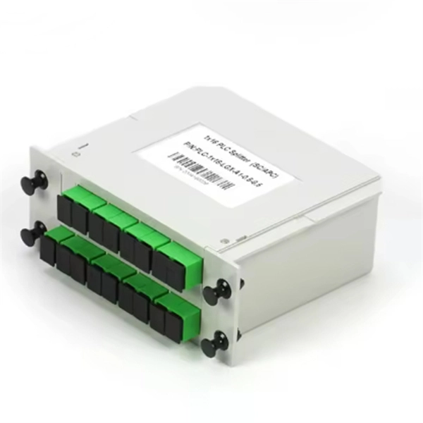
BUS CONNECTORS
Each Swaged Bus connector results in a superior mechanical, thermal and electrical connection for your substation needs.
IEEE 14 Bus Single Line Diagram | PDF
This document contains two diagrams: a single line diagram for a 14 bus system and a single line diagram for a 5 bus system.
I-Line Application Data
These flexible connectors allow for busway expansion and contraction on the low voltage spades. Positioning of these flexible connectors is critical for proper alignment between the busway and

SENTRON Busway Systems
Siemens Power II Fit (P II F) Program compensates for dimensional deviations that may result in busway layouts. With the P II F Program, specific dimensions on straight sections and/or elbows may
Wiring Diagrams with ConceptDraw DIAGRAM
A wiring diagram is a comprehensive diagram of each electrical circuit system showing all the connectors, wiring, terminal boards, signal connections (buses) between the devices and electrical or
TRACK BUSWAY INSTALLATION, OPERATION, AND
track busway system, hereafter referred to as Track Busway. The system shall be designed p. imarily for overhead power distribution of electrical power. Once installed, the Track Busway will provide simple,
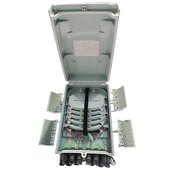
Substations – Volume III – Conductors & Bus
Copper or electrical bronze connectors should be utilized with copper conductors. All-aluminum connectors should be used with aluminum conductors. Compression connections are used in splicing
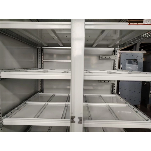
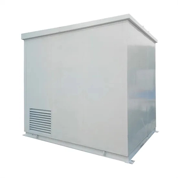
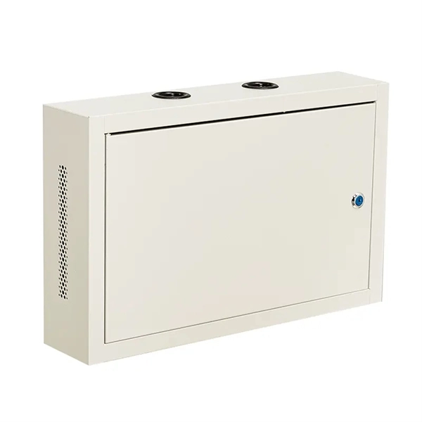
Micro-Modular & Edge DC
Prefabricated micro-modular data centers and edge pods, scalable from 5 to 50 racks, ready for 5G and edge AI workloads.
Immersion & Liquid Cooling
Single-phase immersion cooling tanks and direct-to-chip liquid cooling switches, achieving PUE below 1.1.
AI Servers & Racks
GPU-accelerated AI servers, high-density server racks, and network cabinets optimized for AI/ML workloads.
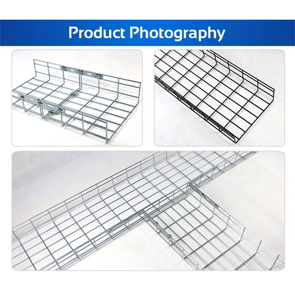
DCIM/EMS & Cable Bridge
Real-time data center infrastructure management, plus overhead cable trays and fiber bridges for structured cabling.