Best Practice Guide to Cable Ladder and Cable Tray Systems
Cable ladders and cable trays should be mounted far enough off the floor or roof to allow the cables to exit through the bottom of the cable ladder or cable tray.

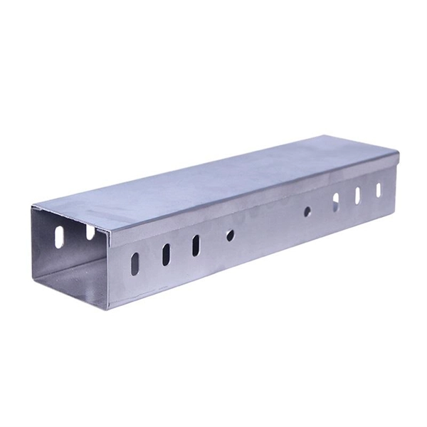
CABLE LADDER SYSTEM
Ladder shall have an overall height of 4” (100 mm). Minimum load depth shall be 3.5” (90 mm). Widths shall be 8”, 12”, 16”, 20” and 24” (200, 300, 400, 500 and 600 mm)
Cable Tray Spacing Standards for Installation and Safety
This article provides an in-depth look at the cable tray spacing standards that should guide your next installation project. Let''s dive deeper into
CABLE TRAY SYSTEMS GUIDE
Some applications may require the cable tray to support the weight of a single, dead object in addition to the cable loads. Specifications typically require this to be applied at the midpoint of the span between
Cable Tray Design and Sizing Guide | PDF | Beam (Structure)
The document discusses key factors to consider when designing a cable tray system, including: 1) Determining the appropriate width and height of the tray based on the cables; 2) Choosing between
A Guide to Installing and Supporting Electrical Cable Trays
This guide covers the critical steps, from selecting the right electrical cable tray and performing accurate cable fill calculations to managing a safe cable pull through
TECHNICAL AND SIZING DATA
The construction and outside diameter of the smallest cable will usually determine either the rung spacing or the type of construction for the bottom of the tray.
B-Line series Cable Tray Design Considerations
For ladder or ventilated trough trays, the total sum of the cross-sectional areas of all the cables to be installed in the cable tray must be equal to or less than the allowable cable area for the tray width, as
CableTray Book English
All calculations and data for AH1-8 series are based on cable tray with rungs spaced on 12" centers with tray supported as simple spans with deflection measured at the midpoint.
Guide to cable support systems
The load capacity of the cable trays according to the support width can be read off in the diagram using load curves – here, shown as an example for a cable tray with the tray widths 100 to 600 mm.
Thomas & Betts Canada
Straight siderail Design: Extruded I-Beam, Nominal Height 4 in. to 7 in., Loading Height 3 in. to 6 in. Snap-in splice plate connection. Reverse position of every other rung for bottom or top mounting of
Document DICOS
To install the cable tray supports, first find the required elevation from the floor to the bottom of the cable tray and establish a level line with a laser or a nylon string.
Micro-Modular & Edge DC
Prefabricated micro-modular data centers and edge pods, scalable from 5 to 50 racks, ready for 5G and edge AI workloads.
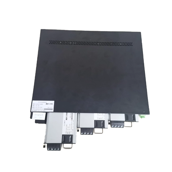
Immersion & Liquid Cooling
Single-phase immersion cooling tanks and direct-to-chip liquid cooling switches, achieving PUE below 1.1.
AI Servers & Racks
GPU-accelerated AI servers, high-density server racks, and network cabinets optimized for AI/ML workloads.
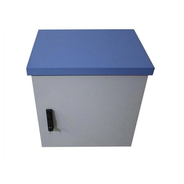
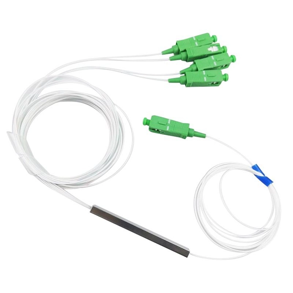
DCIM/EMS & Cable Bridge
Real-time data center infrastructure management, plus overhead cable trays and fiber bridges for structured cabling.