Understanding Fiber Loss: What Is It and How to Calculate It?
This post introduces the main fiber loss types, the calculation process of link loss including fiber attenuation, connector loss, and splice loss, calculating power budget and calculating
Understanding Optical Splitter Loss
Understanding splitter ratios and insertion loss is fundamental to building a reliable fibre optic network. The key takeaway is that every split reduces optical power, and this loss must be
How Many Fiber Connections Are Too Many: Calculating Fiber Link Loss
This article examines how to calculate a fiber optic cable''s link loss budget by identifying loss sources. Testing methods using an OLTS power meter or OTDR are also compared.
Guidelines On What Loss To Expect When Testing Fiber Optic Cables
To be able to judge whether a fiber optic cable plant is good, one does a insertion loss test with a light source and power meter and compares that to an estimate of what is a reasonable loss for that cable
Performing In-Service Loss Measurements in Passive Optical
This application note describes a non-disruptive method for testing optical fibers in an active FTTX network to ensure best network performance and the best customer experience.
How Many Fiber Connections Are Too Many:
This article examines how to calculate a fiber optic cable''s link loss budget by identifying loss sources. Testing methods using an OLTS power meter
How to Calculate Optical Splitter Loss
Understanding optical splitter loss isn''t just about plugging numbers into a calculator. It''s about knowing what factors contribute to that loss, how manufacturers specify it, and how it impacts
GPON power budget calculations | APNIC Blog
One of the key considerations for every GPON designer is the achievable span between the Optical Line Terminal (OLT) and the subscribers — that is, the maximum optical budget allowed
Fibre Optic Cabling Loss Limits Explained – Trend Networks
Learn about fibre optic cabling loss limits & how to calculate them. Gain insights from experts on acceptable loss for cabling projects & explore the standards.
Optical Fiber Loss and Attenuation | MEETOPTICS Academy
Fiber loss, also called fiber optic attenuation or attenuation loss, refers to the loss of signal between input and output. Losses can be introduced by various means such as intrinsic material absorption,

How to Calculate Fiber Loss | Optical Attenuation
Learn what causes fiber optic loss and how to calculate total link loss, power budget, and margin for accurate fiber network design and performance.
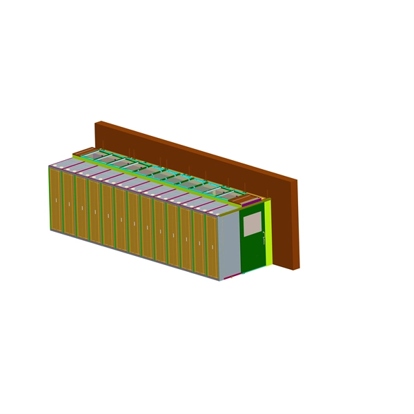
Micro-Modular & Edge DC
Prefabricated micro-modular data centers and edge pods, scalable from 5 to 50 racks, ready for 5G and edge AI workloads.
Immersion & Liquid Cooling
Single-phase immersion cooling tanks and direct-to-chip liquid cooling switches, achieving PUE below 1.1.
AI Servers & Racks
GPU-accelerated AI servers, high-density server racks, and network cabinets optimized for AI/ML workloads.
DCIM/EMS & Cable Bridge
Real-time data center infrastructure management, plus overhead cable trays and fiber bridges for structured cabling.