Fiber Optical Return Loss (ORL) and Reflectance Testing| Fluke
This document discusses the limitations on these optical return loss measurements. There is a limit to the range of values that can be measured for optical reflectance.
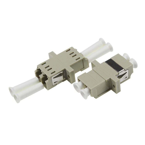
MPO MTP Loss Testing | Kingfisher International
Multimode and single mode fiber systems using MPO/MTP connectors are now common, however users have major questions surrounding MPO cable testing. So, in this article, we go right back to T&M
Multimode MPO and SN-MT Connectors with APC Endface:
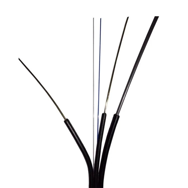
The main contributor to return loss on MM fiber is the Fresnel reflection at the fiber-air interface. When light travels from a higher index (glass core) to a lower index (air at the fiber tip), part of the signal is
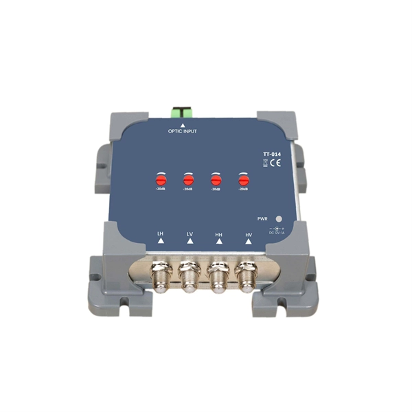
Fiber Optic System Testing Tutorial
Return loss (dB) is a measure of how much power is reflected back to the source from all reflective events in the fiber optic link relative to how much power was launched into the link.
Spring Force Requirements for MPO Connectors
This paper examines the critical parameters, including the spring force and ferrule geometry, needed to achieve physical contact for MT-16 based ferrules and to ensure optimal insertion loss and return

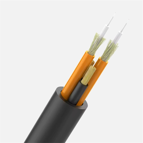
Calculating the loss in a multi-mode link
This chapter describes how to calculate the maximum allowable loss for an fiber optic link that uses multi-mode components. It shows an example of a multi-mode ESCON link and includes a
Calculation Model for Multimode Fiber Connection Using Measured
We propose a calculation model that can be widely used for practical application of multimode optical fiber connections in loss testing of transmission systems.
Guidelines On What Loss To Expect When Testing Fiber Optic Cables
To be able to judge whether a fiber optic cable plant is good, one does a insertion loss test with a light source and power meter and compares that to an estimate of what is a reasonable loss for that cable

MULTIMODE LINK OPTIMIZATION BASED ON RETURN LOSS
The techniques presented herein leverage a return loss (RL) detector to optimize high-speed MMF links, thus enhancing the capability of switches to continuously monitor reflections.
Measure Return Loss in Multimode Fiber-Optic Systems
You can choose from among three methods to measure the return loss of multimode fiber-optic systems: optical continuous-wave reflectometry, optical time-domain reflectometry, and optical
MPO MTP Loss Testing | Kingfisher International
Standards ComplianceGeneric Loss Test Accuracy & Confidence IssuesTest CordsInspection & CleaningCabling DisturbanceContinuity TestingPolarity TestingSo, What Loss Test Uncertainty Can I Expect?For our target use-case (850 nm, OM4, 40G typical transceiver), we deduced that a test accuracy of 0.4 dB is desirable. It appears we can approximately meet this with the following precautions: 1. Use phased install / test approach to minimize cable disturbance. 2. Clean & inspect every time a connector is mated. 3. Perform continuity / polarity /See more on kingfisherfiber Fluke Networks
Fiber Optical Return Loss (ORL) and Reflectance Testing| Fluke
This document discusses the limitations on these optical return loss measurements. There is a limit to the range of values that can be measured for optical reflectance.
Micro-Modular & Edge DC
Prefabricated micro-modular data centers and edge pods, scalable from 5 to 50 racks, ready for 5G and edge AI workloads.
Immersion & Liquid Cooling
Single-phase immersion cooling tanks and direct-to-chip liquid cooling switches, achieving PUE below 1.1.
AI Servers & Racks
GPU-accelerated AI servers, high-density server racks, and network cabinets optimized for AI/ML workloads.
DCIM/EMS & Cable Bridge
Real-time data center infrastructure management, plus overhead cable trays and fiber bridges for structured cabling.