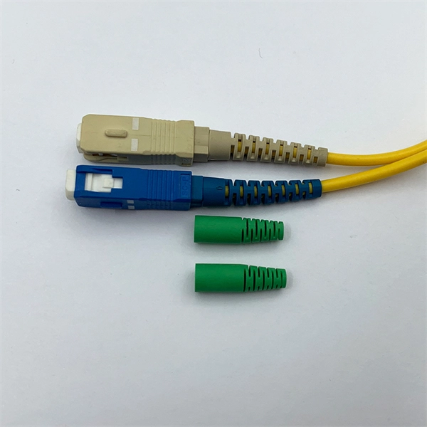
Fiber Insertion Loss and Return Loss: A Complete Guide
In the test report for a fiber cable, you may often see some data related to fiber insertion loss (IL) and return loss (RL), but do you know what insertion loss and return loss actually mean?

Understanding Fiber-Optic Cable Signal Loss, Attenuation, and
To determine the power budget and power margin needed for fiber-optic connections, you need to understand how signal loss, attenuation, and dispersion affect transmission.

Fiber Optical Return Loss (ORL) and Reflectance Testing| Fluke
Know about fiber optical connector return loss (ORL) and reflectance standards measurement calculation, tolerances limits, troubleshooting and testing.
Understanding Fiber Optic Signal Loss & Attenuation
Learn about fiber optic signal loss, its causes, measurement techniques, and strategies to reduce attenuation for high-speed, reliable network performance.
Guidelines On What Loss To Expect When Testing
To be able to judge whether a fiber optic cable plant is good, one does a insertion loss test with a light source and power meter and compares that to an estimate of
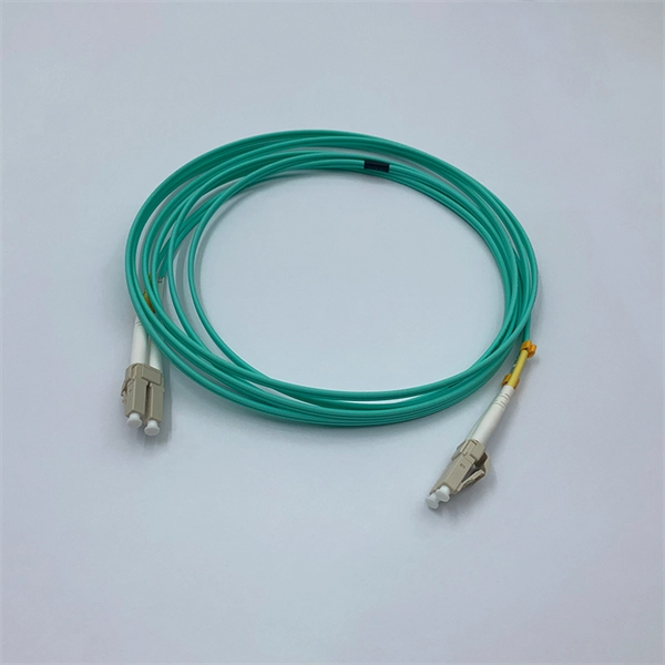
Insertion Loss vs Return Loss in Fiber Optics:
Explore the differences between insertion loss and return loss in fiber optics. Learn key formulas, acceptable values, and factors that affect IL and RL.

Fiber-optic Attenuators – fixed or variable attenuation, working
What is a Fiber-optic Attenuator? Fiber-optic attenuators are a specific type of optical attenuators which are used in fiber optics, e.g. for achieving a suitable signal level for a data receiver in a telecom
How to Calculate Fiber Optic Loss: Key Factors and Standards
Learn how to accurately calculate fiber optic loss to ensure optimal network performance. Explore types of loss, industry standards, and step-by-step methods for assessing link loss and power budget.
Guidelines On What Loss To Expect When Testing Fiber Optic Cables
To be able to judge whether a fiber optic cable plant is good, one does a insertion loss test with a light source and power meter and compares that to an estimate of what is a reasonable loss for that cable
Optical Fiber Loss and Attenuation | MEETOPTICS Academy
Fiber loss, also called fiber optic attenuation or attenuation loss, refers to the loss of signal between input and output. Losses can be introduced by various means such as intrinsic material absorption,
Insertion Loss vs Return Loss in Fiber Optics: Definitions, Formulas
Explore the differences between insertion loss and return loss in fiber optics. Learn key formulas, acceptable values, and factors that affect IL and RL.
Fiber Optic System Testing Tutorial
If abiding by ANSI/EIA/TIA recommendations, this typically includes the insertion loss of two connector pairs (one at each end of the link) and the optical fiber attenuation, and any splice loss in between.
Micro-Modular & Edge DC
Prefabricated micro-modular data centers and edge pods, scalable from 5 to 50 racks, ready for 5G and edge AI workloads.
Immersion & Liquid Cooling
Single-phase immersion cooling tanks and direct-to-chip liquid cooling switches, achieving PUE below 1.1.
AI Servers & Racks
GPU-accelerated AI servers, high-density server racks, and network cabinets optimized for AI/ML workloads.
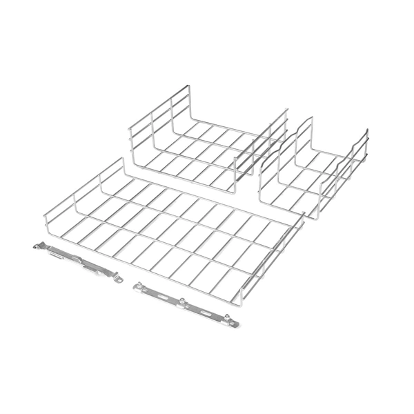
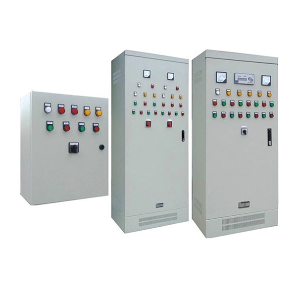
DCIM/EMS & Cable Bridge
Real-time data center infrastructure management, plus overhead cable trays and fiber bridges for structured cabling.